Background
I got inspired by Jonathan Pallants Monotron (talk) project to make to make my own embedded computer. My initial goal was to essentially reimplement the majoroty of the features found on the Monotron, but on a newer and more powerful platform. The platform of choise was the Arduino Portenta H7 with a dual-core STM32H747 MCU. The Portenta H7 has DisplayPort over USB-C, external SDRAM and QSPI flash and a WiFi/Bluetooth module.
The Portenta H7 can run Arduino sketches ontop of the open-source Mbed rtos. Not something I’m interested in as I want to write my own “OS” from scratch in Rust. The MCU boots from address 0x08000000, this is where the bootloader entrypoint is. Arduino sketches are stored at 0x08040000, this is where the bootloader jumps to when all the board setup is done.
The Bootloader Mystery
The bootloader is closed-source. So what?
The bootloader configures the Power management IC (PMIC). This is a chip that provides all voltages to all the components on the board. Without the correct configuration, some parts (especially the ANX7625) will not work.
Martino Facchin, member of the Arduino organization on Github said in this issue that the source will be released soon. That comment was made well over a year ago. Asking for an update on the matter yielded no results.
What we know about the bootloader
- Written in C++ using the mbed rtos.
- Gets the last reset reason and does something.
- Configures the PMIC.
- Exposes a DFU target on the USB-C connection.
- Configures RTC to do something.
- Possibly more?
Let’s focus on the PMIC configuration as it’s the most important part to make things work.
Attempt 1
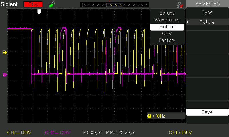
After a quick look at the schematics provided by Arduino, we can see that the PMIC used is a NXP PF1550 which lists I²C as the configuration interface. Using an ocsillisocpe at my university, I captured the SCL and SDA lines and saved the capture to a USB drive. After throwing together a small program to convert the captured data to a format that sigrok could understand, I imported it using the sigrok frontend PulseView. PulseView provides great protocol decoding so getting the data was easy. I got a total of six I²C packets where each packet contained two bytes. Great, I thought and added the six I²C writes to my startup code exptecting the orange DL2 LED on the board to turn off. To my surprise it did not. After looking closer at the data, I could see that at the end of my ocsillisocpe capture, there was a I²C start condition and a partial address. Turns out that the ocsillisocpe I used does not have enough memory to capture the entire boot sequence. Bummer.


Attempt 2
The bootloader is closed-source but Arduino provides compiled bootloader binaries on Github. Great! Let’s open portentah7_bootloader_mbed_hs_v2.elf in iaito to take a look. Thankfully, the bootloader binaries provided are non-stripped elf files with debug information. After jumping to the main label we see some RTC, reset reason, flash, and Digital IO calls. None of which are particularly interesting. A bit further down we see a call to mbed::I2C::I2C(PinName, PinName). After this, I counted twelve calls to mbed::I2C::write(int, char const*, int, bool) which confirmed my suspicion about not capturing all data in my first attempt. Looking at the assembly, it’s not super clear to me what data is being written to the bus. I’m almost confident that the I²C address is stored in R1, data in R2, and data length in R3. Address and data length is no problem to read, however the data written is not obvious to me.
At this point I tried using a debugger to read the registers but failed because the debugger refused to connect.
The following code is repeated twelve times, once for each write.
0x080019f6      movs    r3, 0x4f                            ; main.cpp:240 ; 'O'
0x080019f8      add     r2, var_8h                          ; main.cpp:245
0x080019fa      movs    r1, 0x10                            ; loc.FAULT_TYPE_HARD_FAULT
0x080019fc      strb.w  r3, [var_8h]                        ; main.cpp:243
0x08001a00      add     r0, var_d8h                         ; main.cpp:244
0x08001a02      movs    r3, 2
0x08001a04      str     r4, [sp]
0x08001a06      strb.w  r4, [var_9h]
0x08001a0a      bl      mbed::I2C::write(int, char const*, int, bool) ; main.cpp:245 ; method.mbed::I2C.write_int__char_const__int__bool_
                                                            ; mbed::I2C::write(int, char const*, int, bool) ; method.mbed::I2C.write_int__char_const__int__bool_ ; method.mbed::I2C.write_int__char_const__int__bool_(0xd8, 0x10, 0x8, 0x2, -1)
Attempt 3
At this point I had gotten rather frustrated. I just had to accept the fact that you need the right tool for the job. In this case the tool I needed was a logic analyzer. After some research, the Saleae Logic 8 seemed to be the go to. The 400€ (incl VAT) price was rather steep though. Turns out that Saleae have discounts for students and and non-commercial users. Great.
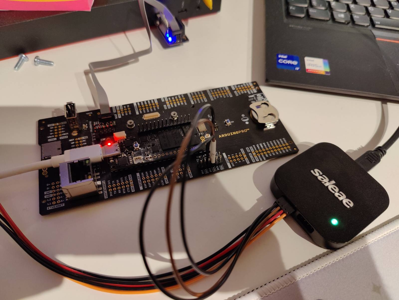
Once my Logic 8 arrived, I hooked it up to the I²C lines and started capturing data. As expected, twelve packets of data were sent by the bootloader.


With all the data captured, I once again tried to configure the PMIC and to my surprise, the DL2 LED turns off and everything works! Now other devices sush as the ANX7625 (MIPI to DisplayPort converter) also work.
Result
Here is a table with all the I²C traffic the bootloader generates:
| Packet | Address (7bit) | R/W | Data | Description |
|---|---|---|---|---|
| 1 | 0x08 | W | 0x4f, 0x00 | LDO2_VOLT: 1.80V |
| 2 | 0x08 | W | 0x50, 0x0f | LDO2_CTRL: VLDO2_EN = 1, VLDO2_STBY_EN = 1, VLDO2_OMODE = 1, VLDO2_LPWR = 1 |
| 3 | 0x08 | W | 0x4c, 0x05 | LDO1_VOLT: 1.00V |
| 4 | 0x08 | W | 0x4d, 0x03 | LDO1_CTRL: VLDO1_EN = 1, VLDO1_STBY_EN = 1 |
| 5 | 0x08 | W | 0x52, 0x09 | LDO3_VOLT: 1.20V |
| 6 | 0x08 | W | 0x53, 0x0f | LDO3_CTRL: VLDO3_EN = 1, VLDO3_STBY_EN = 1, VLDO3_OMODE = 1, VLDO3_LPWR = 1 |
| 7 | 0x08 | W | 0x9C, 0x80 | Not documented? No mention of 0x9C in datasheet. |
| 8 | 0x08 | W | 0x9E, 0x20 | Not documented? No mention of 0x9E in datasheet. |
| 9 | 0x08 | W | 0x42, 0x02 | SW3_CTRL1: SW3_ILIM = 1.5A |
| 10 | 0x08 | W | 0x94, 0xA0 | VBUS Current limit = 1500mA |
| 11 | 0x08 | W | 0x3B, 0x0F | SW2_CTRL: SW2_EN = 1, SW2_STBY_EN = 1, SW2_OMODE = 1, SW2_LPWR = 1 |
| 12 | 0x08 | W | 0x35, 0x0F | SW1_CTRL: SW1_EN = 1, SW1_STBY_EN = 1, SW1_OMODE = 1, SW1_LPWR = 1 |
| 13 | 0x08 | W | 0x42, 0x01 | This write is not part of the bootloader itself but it’s sent just before your Arduino code runs. fixup3V1Rail |
I ended up with code similar to this:
const PMIC_ADDRESS: u8 = 0x08;
const PMIC_SETUP: &[&[u8]] = &[
    &[0x4F, 0x00],
    &[0x50, 0x0F],
    &[0x4C, 0x05],
    &[0x4D, 0x03],
    &[0x52, 0x09],
    &[0x53, 0x0F],
    &[0x9C, 0x80],
    &[0x9E, 0x20],
    &[0x42, 0x02],
    &[0x94, 0xA0],
    &[0x3B, 0x0F],
    &[0x35, 0x0F],
    &[0x42, 0x01],
];

fn configure<E, BUS: I2CWrite<Error = E>>(bus: &mut BUS) -> Result<(), E> {
    for data in PMIC_SETUP {
        bus.write(PMIC_ADDRESS, *data)?;
    }
    Ok(())
}

let mut i2c_bus = dp.I2C1.i2c(
    (
        gpiob.pb6.into_alternate_af4().set_open_drain(),
        gpiob.pb7.into_alternate_af4().set_open_drain(),
    ),
    100.khz(),
    ccdr.peripheral.I2C1,
    &ccdr.clocks,
);

// Configure PMIC (NXP PF1550)
configure(&mut i2c_bus).unwrap();
Data captures and more documentation can be found at olback/h7-bootloader-rev. Project that started it all: olback/h7.
Final thoughts
This blog post is just scratching the surface of the Portenta H7 bootloader, it should be enough to get you going on platforms other than the Arduino IDE.
Arduino
While I appreciate open-source hardware and software, I find it rather annoying when companies like Arduino go almost all the way. Especially with a device like this, a device aimed at “pros” who probably won’t use the Arduino IDE to write production code. The lack of communication from Arduinos side is also quite disappointing.
Saleae Logic 8
Since I purchased a Saleae Logic 8 for this project, here are some thoughts:
It’s a brick, but in a good way. The housing is all metal, giving the device some heft and a premium feel. The included wires are nothing like the cheap jumpers you’re used to. These a soft, very bendy wires with a good feling. The Logic2 software is really easy to use. No wierd layouts or quirks. Community extensions are supported which is super nice. The only thing I’m not a fan of is that Logic2 is written using Electron. Wish it was a “native” application but since the performance is surprisingly good, I’ll let it slide.
If you’re a hardware tinkerer and don’t already have a logic analyzer or an ocsillisocpe with serial decode, I think you should consider getting one. You get ~50% off if you’re a student.